LANCOM Publikationen
Dokumentationen, Papers, Handbücher und Visio Shapes.
Alle Veröffentlichungen und Anleitungen an einem Ort.
Alle LANCOM Veröffentlichungen zur Hand
Sie sind auf der Suche nach einem bestimmten Dokument? Auf dieser Seite haben wir unsere Veröffentlichungen übersichtlich für Sie aufbereitet. In den Kategorien LCOS-Dokumentation, Infopaper, Techpaper, Whitepaper, Handbücher, Visio Shapes und Logos / Bilder stehen viele nützliche und hilfreiche Downloads für Sie bereit.
Alles auf einen Blick
Schon gelesen?
Flyer
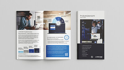
Broschüren
Studien
Studie „Digitale Souveränität“ als Leseprobe oder komplette Studie anfordern
Studie „Cybersicherheit für IT-Netzwerke unter NIS2“ als Leseprobe oder komplette Studie anfordern
Studie „Campusvernetzung“ als Leseprobe oder komplette Studie anfordern
Studie „Digitalisierung der Verwaltung in ostdeutschen Bundesländern“ als Leseprobe oder komplette Studie anfordern
Studie „Cyber Security neu gedacht“ als Leseprobe oder komplette Studie anfordern
Studie „WLAN out of the Box“ als Leseprobe oder komplette Studie anfordern
Studie „Modernes Netzwerkmanagement“ als Leseprobe oder komplette Studie anfordern
Studie „Moderne Standortvernetzung“ als Leseprobe als komplette Studie anfordern
Studie „IT-Trends 2024 kennen und einbeziehen“ als Leseprobe oder komplette Studie anfordern
EHI-Studie „POS-Systeme 2024“ als Sonderauswertung für LANCOM anfordern
Infopaper
WLAN
Digitale Souveränität
Techpaper
LANCOM Management Cloud
Switches
Whitepaper
Standortvernetzung
Whitepaper: Post-Quantum VPN Security
Whitepaper: 5G – Mobilfunk der Zukunft
Whitepaper: Session Border Controller
Whitepaper: Session WPA3 & Enhanced Open
Whitepaper: Breitbandausbau mit Glasfaser
Whitepaper: Der neue WLAN-Standard Wi-Fi 7
Whitepaper: WLAN-Standard Wi-Fi 6E
Whitepaper: WLAN-Standard Wi-Fi 6
Whitepaper: 2x2 Wi-Fi 6 vs. 3x3 Wi-Fi 5
Whitepaper: Virtualisierung von Netzwerkfunktionen (NFV)
Whitepaper: WLAN-Betriebsmodelle
Whitepaper: Retail-Vernetzung als Leseprobe oder komplettes Whitepaper anfordern
LCOS-Betriebssysteme
LCOS
HTML-Versionen:
LCOS FX
HTML-Versionen:
LCOS LX
HTML-Versionen:
LCOS SX
HTML-Versionen:
Visio Shapes
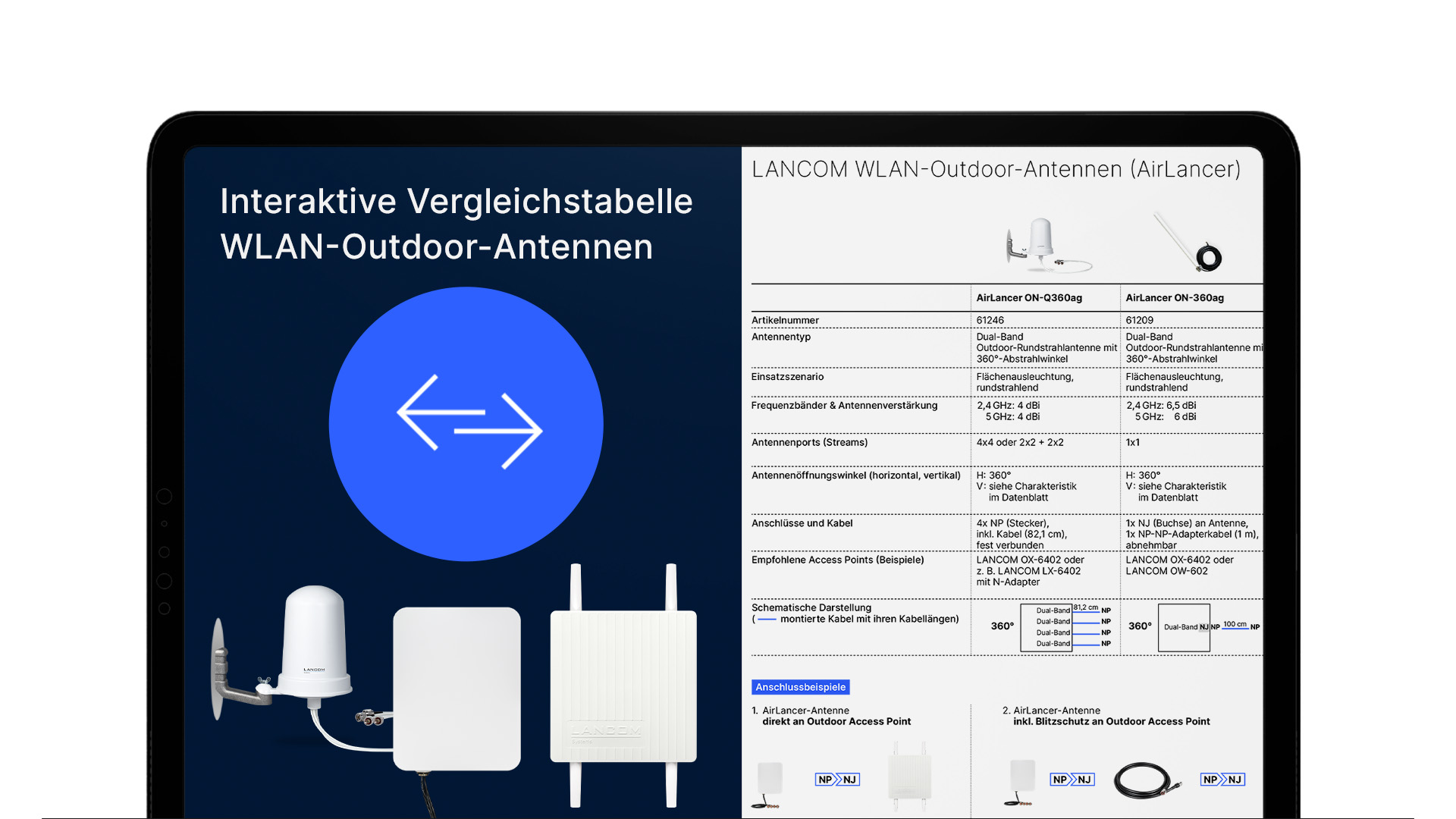
Sie finden die einzelnen Visio Shapes (.vss-Dateien) als Direktdownload im interaktiven PDF oben oder ansonsten auf den einzelnen Produktwebseiten mit Klick auf die Geräte-Zeichnung.
Handbücher
Hilfreiche Links
Ihr direkter Draht zu uns

Die meisten Fragen lassen sich im direkten Kontakt am besten klären:
Wir freuen uns darauf, Ihre Fragen und Wünsche telefonisch oder über das Kontaktformular zu beantworten.
Vertrieb Deutschland
+49 (0)2405 49936 333 (D)
+49 (0)2405 49936 122 (AT, CH)


